RF tube Shutter Bypass Procedure
⚠ STOP — READ BEFORE PROCEEDING: SAFETY DOWNGRADE NOTICE

Performing this procedure removes the laser shutter and disables shutter detection. Doing so reverts your machine from a Class I laser product to a Class II laser product for the duration of the test.
A Class II configuration is the architecture that the overwhelming majority of enclosed CO₂ lasers in this category have shipped with for years, and it remains very safe: the door/lid interlock and the X/Y/Z motion protections stay fully active and independent of the shutter. The machine still will not fire with a door open under normal circumstances. However, the classification change is real, and you are responsible for understanding and accepting it.
By performing this procedure you acknowledge that you: (1) understand the machine is being temporarily downgraded to Class II; (2) accept full responsibility for operating it in this state; (3) will notify every other employee or operator with access to this machine that the shutter has been removed and the machine is temporarily Class II; and (4) will restore the shutter and the Class I configuration when testing is complete, following the restore section at the end of this article.
Removing the Laser Shutter for Diagnostic Testing (Class I Bolt, Titan & Compatible Machines)
Overview
On Class I Bolt and Titan series machines, a mechanical shutter sits at the exit of the laser tube and physically blocks the beam when the machine is idle or a door is open. The shutter is located inside an enclosed, protected area of the tube box, so it is not visible during normal operation.

Firmware requirement: The procedure below depends on a touchscreen option called Shutter Status Detection, which lives under Factory Setting. Machines manufactured in 2026 or later ship with the shutter installed and the firmware that exposes the Factory Setting menu.
Some 2025 machines were shipped with the shutter and the original 2025 firmware did not include the Factory Setting menu. If you do not have the Factory Setting menu, you will need to update the firmware before this procedure can be performed. Contact Technical Support if you need help confirming or updating your firmware.
In rare cases, a faulty shutter may fail to fully open when a job runs — partially or completely blocking the beam. Because the shutter cannot be seen, this can look like a power, tube, or optical problem. This article walks a customer through temporarily removing the shutter and disabling shutter detection so that a comparison test job can be run with the shutter out of the beam path. The goal is to isolate the shutter as the cause: if the machine cuts/engraves normally (or noticeably better) with the shutter removed, the shutter is the problem and needs to be replaced.
This procedure applies to the Bolt series, Titan series, and any current or future Thunder Laser machine with a 9.X or higher TL Timer, a shutter, and a Class I safety rating (Aurora is excluded). The steps are the same across these machines; only the size of the shutter cover, its exact location, and the number of cover bolts may differ.
Before You Begin
- Read the safety notice above. Confirm you accept the temporary Class I → Class II downgrade and have notified other operators and affected personnel.
- Wear laser safety eyewear rated for the installed laser sources whenever the machine is powered and capable of firing during this test.
- Have a baseline test file ready. Ideally, run your test cut or engrave before removing the shutter so you have a "before" result to compare against the "after" result. Use the same material, settings, and file for both runs.
- Tools required: a 2.5mm Allen (hex) wrench L shape— straight/standard tip, not a ball-end — and your machine door key.
- Keep removed parts in a safe place. You will be reinstalling the shutter at the end.
How to Video
Step 1 — Disable Shutter Detection on the Touchscreen (Do This First)
The touchscreen setting must be changed before the shutter is physically removed. If you remove the shutter while detection is still active, the machine will throw a shutter fault and will not run.
Accessing Factory Settings
- On the touchscreen, tap Menu, then select Factory Setting.
- When prompted for a password, enter CC8888.
Changing the Shutter Status Detection Setting
- Scroll to the bottom of the factory options list to Shutter Status Detection.
- By default on a Class I machine, the Open option is checked.
- To bypass the shutter, select the Close option. Selecting Close automatically unchecks Open.
- Exit using the yellow back arrow in the lower-left corner, or the home button at the far left of the top menu bar.
Step 2 — Power Down and Open the Tube Box
- Power off the machine and unplug it from the wall outlet.
- Using your machine door key, unlock and open the rear tube box door.
Possible Hot Shutter: If the shutter has been partially blocking the beam, it may be hot or show discoloration/scorching. Before handling, inspect it visually. If it appears hot or discolored, allow it to cool and use appropriate PPE (heat-resistant gloves) when handling. Do not touch a discolored or scorched shutter with bare hands.
Step 3 — Remove the Shutter
- Locate the shutter cover at the exit of the laser tube. It is a small black cover held on by 2 or 3 socket head cap screws (SHCS) — some machines use only two bolts, others use three.
- Using the 2.5mm Allen wrench, loosen all cover bolts highlighted in the image above. The holes in the cover are not captive, so the cover will lift off freely. Remove the cover to expose the shutter, and set the cover and bolts aside.
- The shutter is held onto the shutter solenoid by two set (grub) screws, also 2.5mm. The two screws are positioned 90° apart and should both be accessible from the top.
- Loosen both grub screws (do not fully remove them). These screws have blue thread locker applied (medium strength — they will release with firm pressure but may feel tight initially), so do not be alarmed when they break loose.Important: Use a straight-tip 2.5mm Allen wrench, not a ball-end wrench. A ball-end tip can snap off in a tight, thread-locked screw.
- Once both grub screws are loosened, slide the shutter off the shutter solenoid and set it aside for safe keeping.
- Close the tube box door and lock the handles.
Step 4 — Power On and Run the Comparison Test
- Plug the machine back in, power it on, and allow it to home.
- Run your test project — ideally the same file, material, and settings you used for the baseline run before removal.
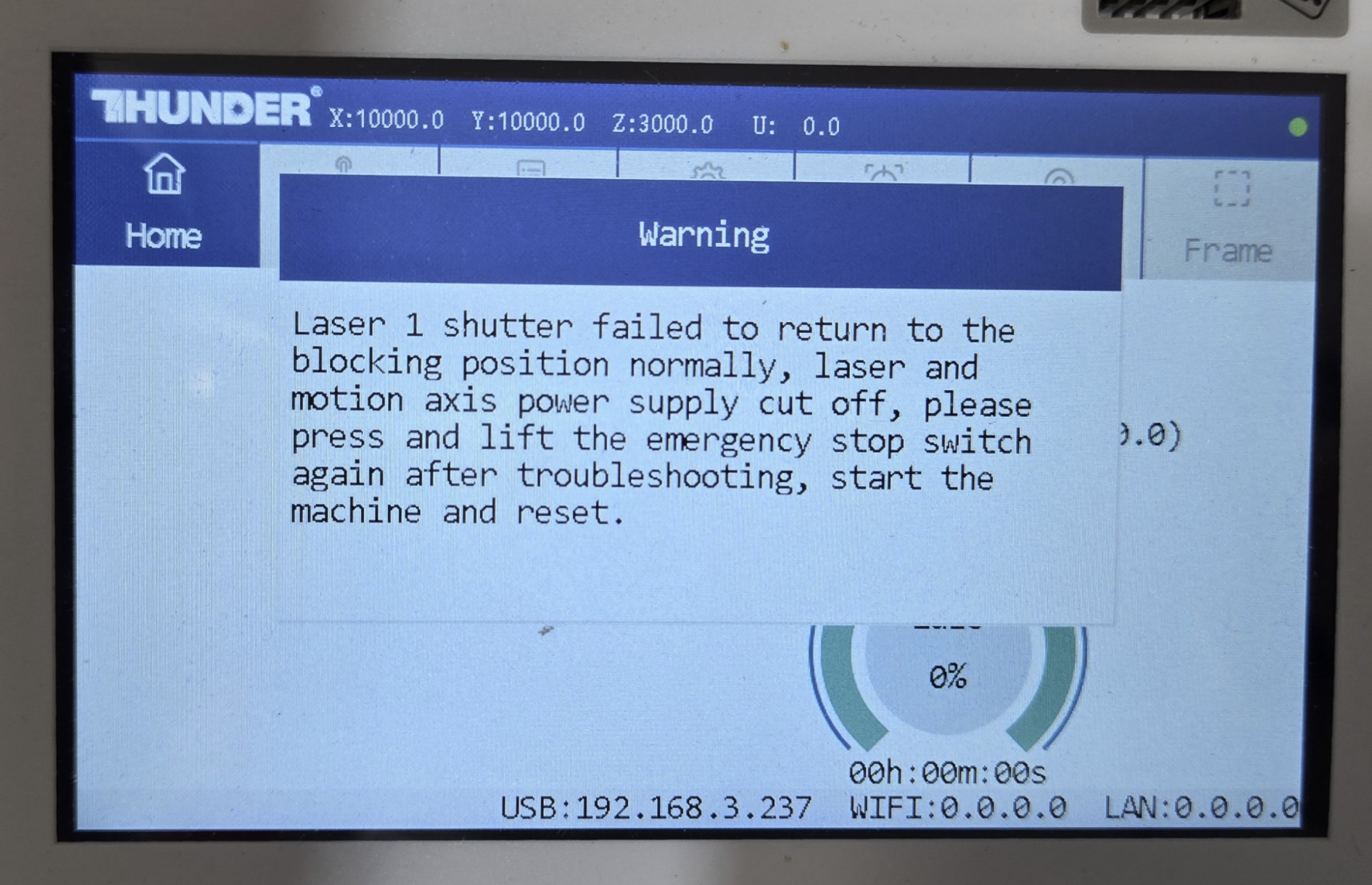
If You Get a Shutter Error
If the machine displays a shutter error message, the factory setting was most likely not changed correctly.
To recover:
- Power off the machine and reinstall the shutter (see the restore section below).
- Repeat Step 1 and confirm Shutter Status Detection is set to Close.
If the error persists after confirming the setting is correctly on Close, stop the procedure and reinstall the shutter. A persistent shutter fault with detection set to Close usually points to a deeper issue — a faulty shutter sensor, a damaged sensor cable, or a controller-side problem — rather than something the operator can resolve in the field. Restore the machine to its Class I configuration (re-select Open in Shutter Status Detection) and contact Technical Support with a description of the symptoms and any error codes shown on the touchscreen.
Reading the Results
If the machine homes normally and runs, compare the result against your baseline:
- Does the project now produce a satisfactory result?
- Does it appear to cut with more power, or engrave deeper/darker than before?
- If the shutter had been fully blocking the beam, then any laser output on this test run is a clear indication the shutter was the cause.
If output is noticeably improved with the shutter removed, the shutter was obstructing the beam (fully or partially) and should be replaced. If there is no change, the cause likely lies elsewhere — contact Technical Support with your findings.
Restoring the Shutter and Class I Configuration
When testing is complete, reverse the procedure to return the machine to its Class I configuration.
- Power off and unplug the machine. Unlock and open the rear tube box door.
- Slide the shutter back onto the shutter solenoid. As you install it, pay attention to the trigger arm for the shutter sensor — it must rest between the forks of the sensor before you tighten the set screws.
- Confirm there is a small gap (around 1/8th inch / ~3mm) between the shutter and the shutter solenoid mounting plate so that the shutter does not rub. Then tighten both set screws.
- Reinstall the shutter cover and tighten all cover bolts.
- Close and lock the tube box door.
- Power the machine on. Go to Menu → Factory Setting (password CC8888), scroll to Shutter Status Detection, and select Open to re-enable detection.
- Exit the menu, allow the machine to home, and confirm it operates normally. The machine is now restored to its Class I configuration*.
*As long as all other Class I options remain installed and operational on the machine.
Reference Links
Related Articles
How to Clean RF Tube Air Filters on a Thunder Laser Bolt and Odin Series machines
Preface: This article covers how to clean your air filters for your RF Tube on your Thunder Laser Bolt and Odin Machine While performing this work, the machine should be powered off. Do not run your machine without the filters installed. Quickstart ...RF Tube and Fan Board Testing
RF Tube and FanBoard Testing Note: You will need a MultiMeter, Small piece of thin wire(4-6") stripped at both ends. To run a dummy file and meter the controller signal wire you will need to bypass the door interlock sensors. Jumper test for signal ...How to convert your Laser machine to a higher Wattage Laser Tube between 80, 100 and 130 watts of Power - What all you will need
Preface: This Article covers what all you would need to convert a given machine to a different wattage laser tube. Note that the mounting of the power supplies will require you to drill and tap holes as the replacements are generally larger. After ...RF Tube- Change from Pre-Ignition to no pre-ignition
⚠ STOP — READ BEFORE PROCEEDING This procedure changes protected vendor-level laser settings, and the optional tuning in Part 2 can cause the tube to emit while the machine is idle. An external pre-ignition value that is set too high will make the ...Titan: Iradion RF Laser Tube Manual and Datasheet
Preface: These documents cover both the Iradion series of tubes in the Titan series. Note that the part number for the tube will have an F for fan appended to it. When reading the documents, the F may be left off. For the latest versions, see the OEM ...